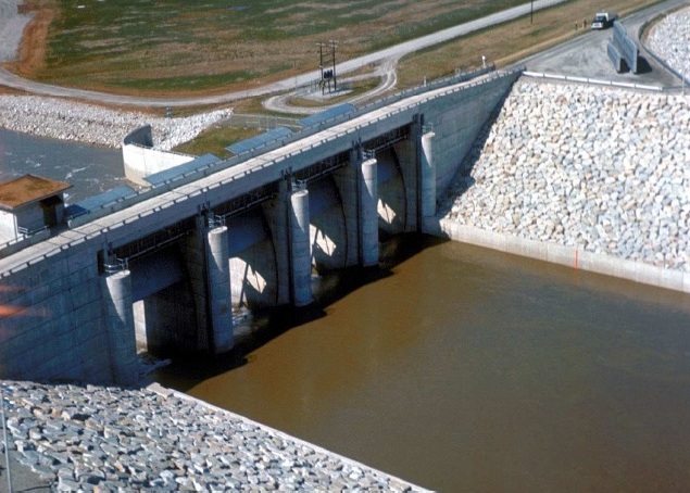
Category Archives: WATER RESOURCE ENGINEERING 2

TYPES OF WEIRS AND FLOW OVER WEIRS


What is a weir?

A weir is a concrete or masonry structure which is constructed across the open channel (such as a river) to change its water flow characteristics. Weirs are constructed as an obstruction to flow of water. These are commonly used to measure the volumetric rate of water flow, prevent flooding and make rivers navigable.

https://d-118701993659849799.ampproject.net/1480633190770/frame.html#adClient:ca-pub-0788339457416941,adSlot:2954917528,ampSlotIndex:0,width:300,height:250,type:adsense,_context:referrer:https://www.google.co.in/,canonicalUrl:http://theconstructor.org/water-resources/what-is-weir-types-flow-over-weirs/11873/,pageViewId:652,location:href:https://cdn.ampproject.org/v/theconstructor.org/water-resources/what-is-weir-types-flow-over-weirs/11873/amp/?amp_js_v=6#-,tagName:AMP-AD,mode:localDev:false,development:false,minified:true,lite:false,test:false,version:1480633190770,rtvVersion:011480633190770,canary:false,hidden:false,amp3pSentinel:1-350257279313413177,initialIntersection:time:1481122296414,rootBounds:left:0,top:0,width:360,height:512,bottom:512,right:360,x:0,y:0,boundingClientRect:left:30,top:124,width:300,height:250,bottom:374,right:330,x:30,y:124,intersectionRect:left:30,top:124,width:300,height:250,bottom:374,right:330,x:30,y:124,intersectionRatio:1,domFingerprint:1340388052,startTime:1481122296407,clientId:CyRDhbk3avvDfGXGpk_fho6ma3bh1CicU-ssvljIFiVJbMZ5vqYOl9qpSjyEiTI-,container:null

Types of Weirs:

Weirs are classified according to:

1. Types of Weirs based on Shape of the Opening

  • Rectangular weir
  • Triangular weir
  • Trapezoidal weir

2. Types of Weirs based on Shape of the Crest

  • Sharp-crested weir
  • Broad- crested weir
  • Narrow-crested weir
  • Ogee-shaped weir

3. Types of weirs based on Effect of the sides on the emerging nappe

  • Weir with end contraction (contracted weir)
  • Weir without end contraction (suppressed weir)

Classification Based on Shape of Opening

Rectangular weir:

  • It is a standard shape of weir. The top edge of weir may be sharp crested or narrow crested.
  • It is generally suitable for larger flowing channels.

Flow over rectangular weir:

To find the discharge over rectangular weir, consider an elementary horizontal strip of water thickness dh and length L at a depth h from the water surface.

Area of strip = L x dh

Theoretical velocity of water

Therefore, discharge through strip

Where Cd = coefficient of discharge

By integrating above equation with limits 0 to H we can get the total discharge Q.

Finally discharge over the weir

Triangular weir:

  • The shape of the weir is actually reverse triangle like V. so, it is also called V-notch weir.
  • This type of weirs are well suitable for measuring discharge over small flows with greater accuracy.

Flow over triangular weir

Here also consider an elementary horizontal strip of water of thickness dh at a depth h from the water surface.

Therefore, area of strip

Theoretical velocity of water

Therefore, discharge through strip dQ = Cd x area of strip x velocity of water

By integrating the above equation with limits 0 to H we can get the total discharge Q.

Therefore,

Finally, we get

Trapezoidal weir:

  • Trapezoidal weir is also called as Cippoletti weir. This is trapezoidal in shape and is the modification of rectangular weir with slightly higher capacity for same crest strength.
  • The sides are inclined outwards with a slope 1:4 (horizontal : vertical)

Flow over cippoletti weir or trapezoidal weir

In cippoletti weir both sides are having equal slope. So, we can divide the trapezoid into rectangle and triangle portions.

So, Total discharge over trapezoidal weir Q = discharge over rectangular weir + discharge over triangular weir

Classification according to shape of the crest:

Sharp-crested weir

  • The crest of the weir is very sharp such that the water will springs clear of the crest.
  • The weir plate is bevelled at the crest edges to obtain necessary thickness. And weir plate should be made of smooth metal which is free from rust and nicks.
  • Flow over sharp-crested weir is similar as rectangular weir.

Broad-crested weir:

  • These are constructed only in rectangular shape and are suitable for the larger flows.
  • Head loss will be small in case of broad crested weir.

Narrow-crested weir:

  • It is similar to rectangular weir with narrow shaped crest at the top.
  • The discharge over narrow crested weir is similar to discharge over rectangular weir.

Ogee-shaped weir:

  • Generally ogee shaped weirs are provided for the spillway of a storage dam.
  • The crest of the ogee weir is slightly rises and falls into parabolic form.
  • Flow over ogee weir is also similar to flow over rectangular weir.

Classification based on end contractions:

Contracted weir

The crest is cut in the form of notch and then it is similar to rectangular weir. Head loss will occur in this type.

Suppressed weir

The crest is running all the way across the channel so head loss will be negligible.

DESIGN OF LINED CANALS

The lined canals are not designed making use of Lacey or Kennedy Theory because the section is rigid. Generally Manning’s equation is used in design. To carry a certain discharge number of channel sections may be designed with different bed widths and side slopes. But it is clear that each section is not equally good for the purpose.

The section to be adopted should be economical and at the same time it should be functionally efficient. It has been found that the most suitable cross-section of a lined canal is a circular section with sloping sides. That is, the bed is not flat but it is an arc of a circle. This arc is tangential to the sloping sides.

Design of Lined Canals

Side Slopes:

The side slope is selected in such a way that it nearly equals the angle of repose of the soil in the subgrade. Care is taken to ensure that no earth pressure is exerted on the back of the lining. From the knowledge of hydraulics it is clear that the section is economical when cross- sectional area is maximum for minimum wetted perimeter.

ADVERTISEMENTS:


This condition is achieved when the centre of an arc lies at FSL of the canal. This section is also efficient in the sense that as the velocity of flow is higher silt carrying is also higher than a wide and shallow section. Thus the problem of silting is completely eliminated and functioning is efficient.

It may be mentioned here that such section with circular bed may be designed up to a discharge of 85 m3/sec. When the discharge is more than 85 m3/sec the section best suited is one with a flat bed and sloping sides with rounded corners. This section is certainly better than trapezoidal section, because it is more stable and economical to construct. Dimensions of a canal section with circular bed may be obtained from the equations given below. Figure 10.2 shows the canal sections of this type with two standard side slopes.

When r = 3.6 m or less, side slopes may be taken 1: 1

ADVERTISEMENTS:


When r = 3.6 m side slopes may be taken 1.25: 1

Velocity of Flow:

Mean velocity of flow may be calculated using Manning’s formula.

V = 1/N .R2/3. S1/2

where N is coefficient of rugosity and may be taken as 0.018

ADVERTISEMENTS:


S is the slope of bed and expressed in fall of bed in m in 10,000 m length

For the given value of N formula may be reduced to

V = 0.556 R2/3. S1/2

where V is velocity of flow in m/sec;

ADVERTISEMENTS:


R is hydraulic mean radius in m; and

S is bed slope expressed in metres/metre length,

since (10,000)1/2 is merged in the constant 0.556.

Following Table 10.1 gives the sectional data for the two side slopes:

Sectional Data of Slopes

Dimensions of a canal section with flat bottom may be obtained from the equations given below. Figure 10.3 shows the cross-sections of this type with two standard side slopes. It may be mentioned here that generally maximum velocity of flow is recommended to be 2 m/sec and Lacey’s ‘f is limited to 1.2. When r exceeds 55 m or when discharge is more than 85 m3/sec, the canal should be designed with a flat bottom with fillets at corners. The Indian Standard 4745 in fact does not suggest lined canal with circular bottom.

Velocity of Flow:

Mean velocity of flow may be calculated from Manning’s formula for value of N = 0.018.

Then V = 0.556 R2/3. S1/2

Following Table 10.2 gives sectional data for the two side slopes:

It may be remembered that lined canal could be given steep slope to achieve recommended velocity of 2 m/sec and value of ‘f’ about 1.2. Critical velocity ratio is not applicable to lined canals. But to avoid possibility of sitting CVR should be aimed at more than unity.

Coefficient of Rugosity (N):

In general practice for lined canal average value of N may be taken as 0.018. For different types of linings the value of W varies. The values given for straight channels in Indian Standard 4745 are given in Table 10.3. When the alignment is not straight loss of head increases and a small increase in the value of W may be made to allow for additional loss of energy.

Freeboard:

Freeboard is measured from the (FSL) full supply level to the top of lining. For lined canals having less than 10 cumec discharge 0.6 m free board is recommended. For bigger lined canals freeboard not less than 0.75 m is generally provided.

Bank Widths:

The Indian Standard recommended following values for bank widths for main and branch canals:

Main canal in cutting and filling = 8.0 m

Branch canal in cutting = 6.5 m

Branch canal in filling, left bank = 6.5 m

Right bank = 5.0 m

Bank widths

Coefficient of Rugosity (N)

Suitable provision of dowel, roadway, catch water drain, under drainage has to be made for every lined canal. Figure 10.4 shows three typical cross-sections of the lined canal in which provision of various components is illustrated.

The canal sections shown have trapezoidal shape. For circular bottomed canal arrangement will be similar. It may be noted that angle 0 shown in the section varies with the side slopes adopted. 9 for side slope 1: 1 has 45° value and for 1.25: 1 is 38° 40′ as shown in Fig. 10.3. Maximum height of the spoil bank is limited to 6 m when the excavation is done by machinery. In case work is accomplished manually maximum height is to be restricted to 4 m only. Also when a canal section in filling involves more than 10.5 m filling each section shall be designed and tested for stability.

Design of Lined Canals

Problem:

Design an irrigation lined canal to carry a discharge of 34 m3 / sec. The mean diameter of the average soil particles is 0.464 mm. Assume side slopes 1.25 : 1 and width zero.

Designing an Irrigation Channel

Typical Cross Sections of Lined Canals

ESTIMATION OF EVAPOTRANSPIRATION

The hydrologic budget for a catchment in a given duration can be written as

•This water budget can be used to estimate AET, if other terms are known or measured or estimated.

Measurement of ET

For a given type of vegetation, ET can be measured

– Using Lysimeters

– From Field Experimental Plots

– From Soil Moisture Depletion Studies etc

Lysimeters

• A lysimeter is a special water tight tank containing soil and set in a cropped field (so buried that the level of soil is the same both inside and outside the container). The same type of plants as in the surrounding field are grown in a lysimeter. The soil in the lysimeter along with the vegetation in it is hydrologically isolated from the surrounding soil. Lysimeters shall be designed so as to accurately reproduce the soil and soil moisture conditions, type and size of vegetation etc of the surrounding area.

• Lysimeter studies involve growing crops in large containers and measuring the water losses and gains. ET can be estimated by determining the amount of water required to maintain constant soil moisture conditions within the tank.

• Types of Lysimeters

– Weighing Type

– Non-weighing Type

• Limitations of Lysimeters

– Reproduction of physical conditions in field (say, temperature, water table position, soil texture, density etc)

Field Experimental Plots

The different elements of the water budget (other than ET) in a known interval of time are measured in special experimental plots established in the field. ET is then estimated as

ET = Precipitation + Irrigation Input – Runoff – Increase in Soil Moisture Storage – Groundwater Loss

• Since groundwater loss due to deep percolation is difficult to measure, it is minimised by maintaining the soil moisture condition in the plot at field capacity.

• This method provides fairly reliable results.

Evapotranspiration Equations

• A number of methods are available to estimate the potential evapotranspiration (PET) using climatological data

• These formulae range from those backed by theoretical concepts to purely empirical methods

• Penman’s equation is based on sound theoretical reasoning and is obtained from a combination of the energy balance and mass transfer approach

• A modified form of the original Penman equation is discussed here

Penman’s Equation

Surface

Range of r values

Close ground corps

0.15 to 0.25

Bare lands

0.05 to 0.45

Water surface

0.04

Snow

0.45 to 0.95

• To compute PET, data pertaining to , mean air temperature, and nature of the surface(ie. the value of albedo) are needed

• These are obtained from actual measurements or using the available meteorological data of the region

• Penman’s equation can be used to compute evaporation from an open water surface by putting r=0.05 in the above equation

Empirical Formulae

• A large number of empirical formulae are available to estimate PET, using climatological data

• These formulae are not universally applicable to all climatic zones

• To be used with caution

• Blaney-Criddle and Thornthwaite Formulae

Blaney-Criddle Formula

• A purely empirical formula developed based on data from arid Western US

• Assumes that PET is related to the hours of sunshine and temperature (these are measures of solar radiation in an area)

• PET (in cm) in a crop growing season

Thornthwaite Formula

• Developed from data of Eastern US

• Uses only mean monthly temperature along with an adjustment for day length


RESERVOIR SEDIMENTATION

Reservoir Sedimentation:

Reservoir sedimentation is filling of the reservoir behind a dam with sediment carried into the reservoir by streams. The flow of water from the catchment upstream of a reservoir is capable of eroding the catchment area and of depositing material either upstream of the reservoir, or in the still water of the reservoir. The nature of the material in the catchment area and the slope of the catchment area and the inlet streams are a factor, as is the nature of the ground cover. Heavy rainfall falling on erodible material on a steep slope with little ground cover resulting from overgrazing or wildfire is a recipe for substantial sediment transport and significant reservoir sedimentation. The formation of gullies can also be anticipated if streambed conditions are suitable.

JNTUH WRE-2 SYLLABUS

CIVIL ENGINEERING 2013.14

JAWAHARLAL NEHRU TECHNOLOGICAL UNIVERSITY HYDERABAD

4-l Sem
(A70133) WATER RESOURCES ENGINEERING-ll

UNIT-1

Storage Works-Reservoirs – Types of reservoirs, selection of site for reservoir,

Zones Of storage Of a reservoir. reservoir yield, estimation of capacity of Reservoir using mass curve- Reservoir Sedimentation – Life of Reservoir..

Types Of dams, factors affecting selection of type of dam, factors governing selection of site for a dam.

UNIT-ll

gravity dams: Forces acting on a gravity dam, causes of failure of a gravity

jam. elementary prohle and practical profile of a gravity dam, limiting height

gf a low gravity darn, Factors of Safety – Stability Analysis, Foundation for a

Gravity Dam, drainage and inspection galleries.

UNlT-lll

Earth dams: types of Earth dams, causes of failure of earth dam, criteria for

safe design of earth dam, seepage through earth dam-graphical method,

measures for control of seepage.

Spillways: types of spillways, Design principles of Ogee spillways – Spillway

gates. Energy Dissipaters and Stilling Basins Significance of Jump Height

Curve and Tail Water Rating Curve – USBR and Indian types of Stilling Basins.

UNIT-lV

Diversion Head works: Types of Diversion head works- weirs and barrages,

layout of diversion head work – components. Causes and failure of Weirs

and Barrages on permeable foundations-Silt Ejectors and Silt Excluders

VVeirs on Permeable Foundations – Creep Theories – Bligh’s, Lane’s and

Khosla’s theories, Determination of uplift pressure- Various Correction

Factors – Design principles of weirs on permeable foundations using Creep

theories – exit gradient, U/s and D/s Sheet Piles – Launching Apron

UNlT-V

Canal Falls -types of falls and their location, Design principles of Notch Fall

and Sarada type Fall.

Canal regulation workS. design Principles Of distributory and head regulators,

Cross Regulators -canal outlets. types of canal modules,

Cross Drainage works: typeS. Selection Of Site. Design principles of aqueduct,

siphon aqueduct and super Passage

DISTRIBUTORY HEAD REGULATOR WORKING MECHANISM


Definition:

The distributary head regulator is constructed at the upstream end (i.e., the head) of a channel where it takes off from the main canal or a branch canal or a major dis-tributary. The distributary head regulator should be distinguished from the canal head regulator which is provided at the canal headworks where a canal takes its supplies from a river source. The distributery head regulator serves to:

  1. Divert and regulate the supplies into the distributory from the parent channel
  2. Control silt entering the distributary from the parent channel
  3. Measure the discharge entering the distributery.

Distributery Head Regulator

Distributery Head Regulator

For the purpose of regulating the supplies entering the offtaking channel from the parent channel, abutments on either side of the regulator crest are provided. Piers are placed along the regulator crest at regular intervals. These abutments and piers have grooves (at the crest section) for the purpose of placing planks or gates. The supplies into the offtaking channel are controlled by means of these planks or gates. The planks are used for small channels in which case manual handling is possible. The span of hand-operated gates is also limited to 6 to 8 m. Mechanically-operated gates can, however, be as wide as 20 m.

An off taking channel tends to draw excessive quantity of sediment due to the combined effects of the following:

  1. Because of their smaller velocities, lower layers of water are more easily diverted into the offtaking channels in comparison to the upper layers of water.
  2. Sediment concentration is generally much higher near the bed.
  3. Sediment concentration near the banks is usually higher because of the tendency of the bottom water to move towards the banks due to difference in central and near bank velocities of flow.

As such, if suitable steps are not taken to check the entry of excessive sediment into the off-taking channel, the offtaking channel will soon be silted up and would require repeated sediment removal. Sediment entry into the off-taking channel can be controlled by causing the sediment to concentrate in the lower layers of water (i.e., near the bed of the parent channel upstream of the off taking point) and then letting only the upper layers of water enter the off taking channel.


Concentration of sediment in lower layers can be increased by providing smooth bed in the parent channel upstream of the off taking point. The smooth channel bed reduces turbulence which keeps sediment particles in suspension. In addition, steps which accelerate the flow velocity near the banks would also be useful. It should also be noted that the alignment of the off-taking channel also affects the sediment withdrawal by the offtaking channel. Hence, the alignment of the offtaking distributary channel with respect to the parent channel needs careful consideration. The angle of off take may be kept between 60° and 80° to prevent excessive sediment withdrawal by the offtaking channel. For all important works, the alignment of offtaking channels should be fixed on the basis of model studies.

For the purpose of regulating the discharge in the distributary, it is essential to measure the discharge for which one can use gauge-discharge relationship of the distributary. However, this relationship is likely to change with the change in the channel regime. Hence, it is advantageous to use head regulator as a metering structure too.

CROSS DRAINAGE WORKS AND AQUEDUCT


Definition:

A cross drainage work is a structure carrying the discharge from a natural stream across a canal intercepting the stream.

Canal comes across obstructions like rivers, natural drains and other canals.

The various types of structures that are built to carry the canal water across the above mentioned obstructions or vice versa are called cross drainage works. There are many different factors involved in selection of a specific type of Cross drainage works and in selection of a suitable site for cross drainage works.

It is generally a very costly item and should be avoided by

  • Diverting one stream into another.
  • Changing the alignment of the canal so that it crosses below the junction of two streams.

Types of cross drainage works

Depending upon levels and discharge, it may be of the following types:

Cross drainage works carrying canal across the drainage:

the structures that fall under this type are: Cross Section of Aqueduct

  1. An Aqueduct
  2. Siphon Aqueduct

Aqueduct:


When the HFL of the drain is sufficiently below the bottom of the canal such that the drainage water flows freely under gravity, the structure is known as Aqueduct.

  • In this, canal water is carried across the drainage in a trough supported on piers.
  • Bridge carrying water
  • Provided when sufficient level difference is available between the canal and natural and canal bed is sufficiently higher than HFL.

Aqueduct

Siphon Aqueduct:


In case of the siphon Aqueduct, the HFL of the drain is much higher above the canal bed, and water runs under siphonic action through the Aqueduct barrels.

The drain bed is generally depressed and provided with pucci floors, on the upstream side, the drainage bed may be joined to the pucca floor either by a vertical drop or by glacis of 3:1. The downstrean rising slope should not be steeper than 5:1. When the canal is passed over the drain, the canal remains open for inspection throughout and the damage caused by flood is rare. However during heavy floods, the foundations are succeptible to scour or the waterway of drain may get choked due to debris, tress etc.

Syphon Aqueduct Construction


Cross drainage works carrying drainage over canal.

The structures that fall under this type are:

  • Super passage
  • Canal siphon or called syphon only

Super passage:

  • The hydraulic structure in which the drainage is passing over the irrigation canal is known as Super Passage
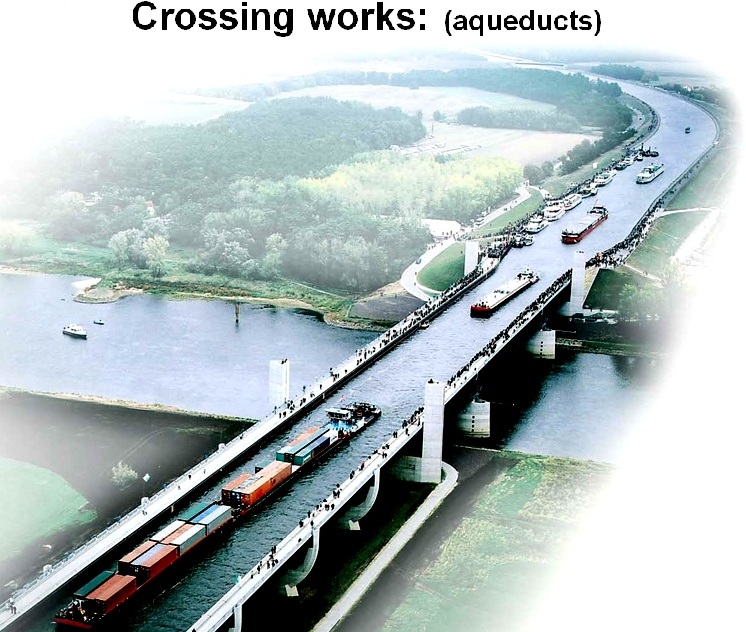
super passage. This structure is suitable when the bed level of drainage is above the flood surface level of the canal. The water of the canal passes clearly below the drainage
  • A super passage is similar to an aqueduct, except in this case the drain is over the canal.
  • The FSL of the canal is lower than the underside of the trough carrying drainage water. Thus, the canal water runs under the gravity.
  • Reverse of an aqueduct

Canal Syphon:

  • If two canals cross each other and one of the canals is siphoned under the other, then the hydraulic structure at crossing is called “canal siphon”. For example, lower Jhelum canal is siphoned under the Rasul-Qadirabad (Punjab, Pakistan) link canal and the crossing structure is called “L.J.C siphon”
  • In case of Siphon Super Passagesiphon the FSL of the canal is much above the bed level of the drainage trough, so that the canal runs under the siphonic action.
  • The canal bed is lowered and a ramp is provided at the exit so that the trouble of silting is minimized.
  • Reverse of an aqueduct siphon
  • In the above two types, the inspection road cannot be provided along the canal and a separate bridge is required for roadway. For economy, the canal may be flumed but the drainage trough is never flumed.

Selection of suitable site for cross drainage works

  • The factors which affect the selection of suitable type of cross drainage works are:
  • Relative bed levels and water levels of canal and drainage
  • Size of the canal and drainage.
  • The following considerations are important
  • When the bed level of the canal is much above the HFL of the drainage, an aqueduct is the obvious choice.
  • When the bed level of the drain is well above FSL of canal, super passage is provided.
  • The necessary headway between the canal bed level and the drainage HFL can be increased by shifting the crossing to the downstream of drainage. If, however, it is not possible to change the canal alignment, a siphon aqueduct may be provided.
  • When canal bed level is much lower, but the FSL of canal is higher than the bed level of drainage, a canal siphon is preferred.
  • When the drainage and canal cross each other practically at same level, a level crossing may be preferred. This type of work is avoided as far as possible.


Factors which influence the choice / Selection of Cross Drainage Works

  1. The considerations which govern the choice between aqueduct and siphon aqueduct are:
  2. Suitable canal alignment
  3. Suitable soil available for bank connections
  4. Nature of available foundations
  5. Permissible head loss in canal
  6. Availibility of funds

Compared to an aqueduct a super passage is inferior and should be avoided whenever possible. Siphon aqueduct is preferred over siphon unless large drop in drainage bed is required.

Classification of aqueduct and siphon aqueduct


Depending upon the nature of the sides of the aqueduct or siphon aqueduct it may be classified under three headings:

Type I:

Sides of the aqueduct in earthen banks with complete earthen slopes. The length of culvert should be sufficient to accomodate both, water section of canal, as well as earthen banks of canal with aqueduct slope.

Sides of the aqueduct in earthen banks, with other slopes supported by masonry wall. In this case, canal continues in its earthen section over the drainage but the outer slopes of the canal banks are replaced by retaining wall, reducing the length of drainage culvert.

Type II:

  1. Sides of the aqueduct made of concrete or masonry. Its earthen section of the canal is discontinued and canal water is carried in masonry or concrete trough, canal is generally flumed in this section.

CANAL HEAD REGULATOR


Structure at the head of canal taking off from a

reservoir may consist of nu ber of spans separated by piers and operated by gates.

Regulators are normally aligned at 90° to the weir. upto 10″ are considered preferable for smooth entry into canal. These are used for diversion of flow. Silt reduces carriage capacity of flow.

Types of regulators in canals

  1. Still pond regulation:
  2. Open flow regulation
  3. Silt control devices

1. Still pond regulation:

  • Canal draws water from still pond
  • Water in excess of canal requirements is not allowed to escape under the sluice gates.
  • Velocity of water in the pocket is very much reduced; silt is deposited in the pocket
  • When the silt has a level about 1/2 to 1m below the crest level of Head Regulator, supply in the canal is shut off and sluice gates are opened to scour the deposited silt.

Canal Head Regulator

Head Regulator

2. Open flow regulation

  • Sluice gates are opened and allow excess of the canal requirement
  • Top water passes into the canal
  • Bottom water maintain certain velocity in the pocket to keep the silt to remain in suspension
  • Canal is not closed for scouring the silt.

3. Silt control devices

  • Silt control at head works:
  • Entry of silt to canal can be controlled by:
  • Providing a divide wall to:
  • Create a trap or pocket
  • Create scouring capacity of under sluices
  • By concentrating the currents towards them
  • Paving the bottom the approach channel to reduce disturbance because due to disturbance sediment remains in suspension


Installing silt excluders

  • Making entry of clear top water by:
  • Providing raised sill in the canal
  • Lower sill level of scouring sluices
  • Wide head regulator reduces velocity of water at intake
  • Smooth entry to avoid unsteady flow
  • Handling careful the regulation of weir
  • Disturbance is kept at minimum in weirs

Silt excluder:

  • Silt is excluded from water entering the canal, constructed in the bed infront of head regulator – excludes silt from water entering the canal
  • Designed such that the top and bottom layers of flow are separated with the least possible disturbance
  • Top water to canal – bottom, silt laden through under sluices
  • No of tunnels resting on the floor of the pocket of different lengths
  • The tunnel near th head regulator being of same length as that of the width of head regulator – tunnel of different length.
  • Capacity of tunnel is about 20% of canal discharge
  • Minimum velocity 2 to 3 m/s to avoid deposition in tunnel is kept the same as sill level of head regulator
  • From discharge and scouring velocity the total waterway required for under water tunnels can be determined،
  • Silt extractor or silt ejector:
  • Device by which the silt, after it has entered the canal is extracted or thrown out.
  • Constructed on the canal some distance away from head regulator
  • Horizontal diaphragm above the canal bed
  • Canal bed slightly depressed below the diaphragm 0.5 to 2.8m
  • Under diaphragm, tunnel which extent the highly silted bottom water tunnel.
  • There should be no disturbance of flow at the entry.
  • Sediment – laden are diverted by curved vanes
  • Forwards the escape chamber: steep slope to escape channel is provided.
  • The streamlined vane passage accelerate the flow through them, thus avoiding deposition (decreasing section area increases the flow velocity)
  • The tunnel discharge by gate at the outlet end (escape channel)

Location:

  • If near head regulator, silt will be in suspension
  • If too far away than result in silting of canal.

DESIGN PRINCIPLES OF HEAD REGULATOR’S


Design Principles for Head Regulators: 14 Principles

Here we detail about the fourteen important design principles for head regulators.

(i) The crest level of the head regulator should be fixed higher than the crest of the under-sluices of the barrage with or without the silt excluder by 1.25 to 2 m to avoid silt entry into the canal.

ADVERTISEMENTS:


(ii) The crest level and the waterway required by the head regulator are interrelated because the discharge to be passed down into the canal and the pond level of the barrage are already fixed.

(iii) Generally for the head regulator broad crest with sloping downstream glacis are provided. So the waterway required can be calculated by corresponding hydraulic formula.

The discharge formula applicable will be:

Q = 1.7(L-knH)H3/2

ADVERTISEMENTS:


where Q = design discharge of the canal in cumec

L = length of waterway in m H = head causing flow in m

k = a constant which varies from 0.01 to 0.03. It depends on the shape of pier nose or cut water,

n = number of end contractions.

ADVERTISEMENTS:


(iv) The regulation of discharge is done by providing gates. The gates can be provided singly or in two tiers, one rising and other falling. The gates are fitted in the grooves made in the pier body walls.

(v) A downstream sloping glacis is provided up to such level that the hydraulic jump occurs on the slope itself under different discharge conditions in similar manner as for sloping glacis of a barrage or a weir.

(vi) The horizontal impervious floor or the cistern beyond the d/s sloping glacis is provided at least for a length, 5 times the maximum height of the jump, i.e., 5 (D2 – D1).

(vii) The canal may remain closed during highest flood. This constitutes worst condition. For such a condition the stability and safety of glacis and floor has to be checked against uplift pressures.

ADVERTISEMENTS:


(viii) A reinforced concrete mat may be adopted to resist uplift pressure to reduce excessive floor thickness otherwise required. Under such conditions if found necessary the piers may be extended beyond the sloping glacis on to the cistern floor to stabilise the mat against bending.

(ix) As uplift consideration necessitates sheet piles or concrete cut-offs may be provided below the regulator floor and the glacis and floor checked for safety against uplift and piping. It is necessary to determine exit gradient and to see that it is within safe limits.

(x) Since the water level on the upstream rises above the pond level upto high flood level a suitable RCC breast wall of sufficient height and strength stretching full waterway of the regulator is required to prevent spilling of flood flows.

(xi) A bridge over the head regulator should be provided to house working platform for operation of gates.

(xii) As provided for the weir RCC block protection (talus) over stone pitching and inverted filter should be provided beyond the upstream and downstream ends respectively of the regulator impervious floor to prevent scouring. Length of d/s talus may vary from 4 to 5 times FSD of the canal.

(xiii) The regulator piers should be designed adopting usual design criteria and should be stable against maximum overturning moment caused by flood flows.

(xiv) The length of the waterway together with width of piers and abutments may be at variance to the bed width of the canal taking off. It is necessary to provide suitable wing walls to smoothly attain full canal section on the downstream.

Figure 19.6 shows a typical section of a head regulator.Typical Section of a Head Regulator

FUNCTIONS OF HEAD REGULATORS, CROSS REGULATOR’S, DISTRIBUTORY HEAD REGULATOR’S


1. Functions of Head Regulators:

It is a structure constructed at the entrance (the head) of the canal where it takes off from the river (Fig. 12.11).

The regulator serves the following purposes:

Head Regulator

i. It regulates the flow of irrigation water enter­ing into the canal.

ADVERTISEMENTS:


ii. It can be used as a meter for measuring the discharge.

iii. It regulates and pre­vents excessive silt entry into the canal.

It consists of a raised crest with abutments on both sides. The crest may be subdivided in various bays by providing piers on the crest. The piers support roadway and a platform for operating gates. The gates control the flow over the crest. They are housed and operated in grooves made in the abutments and piers. Sill of the regulator crest is raised to prevent silt entry. Sometimes the gates are provided in tiers. Then lower tiers may be kept closed to raise the sill of the regulator.

ADVERTISEMENTS:


The head regulator is generally constructed with masonry. It should be founded on a good rock foundation. It should be safe against shear, sliding and overturning. It should be flanked with adequate wing walls. The head regulator should also be given proper protection by providing aprons on upstream and downstream side of the barrel. To prevent seepage cut­off is also essential. To take irrigation water at low velocities waterway of the head regulator should be sufficiently big.

2. Functions of Cross Regulator:

It is a hydraulic structure constructed across the canal to regulate the irrigation water supplies. It may be constructed across any type of canal main, branch or a distributary.

Following considerations make it necessary to construct a regulator across the canal:

(i) When due to inadequate supply the water level is lowered the off-taking channels do not get their proper share. A cross regulator is provided to raise the water level.

ADVERTISEMENTS:


(ii) Sometimes it becomes necessary to carry out some necessary to carry out some repair works on a canal. The cross regulator if existing above that reach of the canal, it can be closed and repairs can be done efficiently.

(iii) Sometimes it is necessary to close the canal below a particular point. Say when there is no demand for irrigation water during a particular period.

(iv) When the costly headwork’s are not constructed in the initial stages, the cross-regulator helps in regulating the canal supplies.

(v) Cross regulators divide long canal reach into smaller ones and make it possible to maintain the reach successfully and efficiently. For efficient functioning they should be spaced 10 to 13 km apart on the main canal and 7 to 10 km on the branches.

ADVERTISEMENTS:


A cross-regulator is often combined with rail or a road bridge. When a fall is available on the canal the cross regulator is constructed as a fall-regulator (Fig. 12.12). The cross- regulator may be flumed at the site. It is similar in construction to the head regulator.

Fall Combined with a Cross Regulator

3. Functions of Distributary Head Regulator:

It is a hydraulic structure constructed at the head of a distributary. This regulator performs the same functions as that of a head regulator.

i. It regulates the supply of the distributary.

ii. It can be used many times as a meter.

iii. It is also a silt selective structure.

iv. Distributary head regulator controls the flow in the distributary. By closing the gates distributary can be dried to carry out repairs or maintenance works.

The points to be considered in design are similar to those considered in the design of a head regulator. Only difference is that the distributary head regulator is much smaller in magnitude as compared to the head regulator. Figure 12.13 shows sectional end view of a distributary head regulator.Distributary Head Regulator