
Category Archives: STRUCTURAL ANALYSIS
TRUSS ANALYSIS USING METHOD OF JOINTS
STRUCTURAL ANALYSIS OF STATICALLY DETERMINED BEAMS
APPSC ASSISTANT EXECUTIVE ENGINEER SYLLUBUS AND EXAM PATTERN
Job Highlights
- 1.1 AP Assistant Executive Engineer Exam Pattern
- 1.2 AP Syllabus for AEE
- 1.3 APPSC AEE Syllabus
- 1.4 Brief Info of APPSC Syllabus – APPSC AEE Exam Syllabus
- 1.5 APPSC AEE Civil Engineering Syllabus 2016
- 1.6 Download APPSC AEE Civil/Mechanical Syllabus
APPSC AEE Syllabus & AP Asst Executive Engineer Exam Pattern is here for download. Download Andhra Pradesh AEE Civil as well as APPSC AEE Mechanical Engineering syllabus along with the Previous papers with the help of direct links.
***APPSC AEE Results Released***
APPSC AEE Syllabus 2016
There are many candidates who are searching for APPSC Asst Executive Engineer Exam Syllabus 2016 can reach the right place. Here on our website recruitment.guru, the information related to APPSC Syllabus for AEE jobs is mentioned below with an attachment for the ease of candidates. Its a great news for all the aspirants who are going to attend the AAPSC AEE Exam. The APPSC has issued the examination syllabus and pattern on its official website.
Download APPSC AEE Exam Hall Ticket 2016
This APPSC AEE Syllabus is helpful for all the contenders who want to get a good score. The candidates will be selected based on their performance in the examination. Once the candidate who will be elected, have a bright future. So guys, please utilise this opportunity to get a good score in the written test. In our page, APPSC AEE Syllabus related to various subjects is available at free of cost. The APPSC will conduct the written exam for the applied candidates from 03-11-2016 to 05-11-2016.

Andhra Pradesh Public Service Commission has recently updated the latest recruitment at its official website. There are nearly 748 jobs in various departments include Mechanical/Civil/Agriculture. The candidates who have been waiting for the AP Government Jobs may use this opportunity and apply before the last date. According to the latest employment news, the online applications are available on the official website from 18th August to 21st September 2016. Interested candidates may also check the official website to check the recruitment notification in detail. You may get the APPSC AEE jobs details like Educational Qualification, Age Limit, Fee Details and Exam Date through the direct link attached on this page.
Click Here To Download APPSC AEE Latest Recruitment
AP Assistant Executive Engineer Exam Pattern
The APPSC Asst Executive Engineer test pattern is tabulated here. The Exam Pattern may explain the details of test date, no of Questions, Marks allocated for each question and test duration, etc.
- It is an Objective Based Written exam.
- The Duration of the Test will 450 Minutes.
- The Test will consist of Three papers.
| S.No | Test Type | Paper | Subject Name | Total Marks | No of Questions | Duration |
| 1. | Objective | Paper I | General Studies & Mental Ability | 150 | 150 | 150 |
| 2. | Paper II | Concerned Subject Civil & Mechanical (Common) OR Agriculture | 150 | 150 | 150 | |
| 3. | Paper III | Civil OR Mechanical OR Agriculture | 150 | 150 | 150 |
AP Syllabus for AEE
The APPSC AEE Exam Syllabus Covered Topics are enclosed here for the guidance of the candidates. Refer AP Civil Engineer Syllabus for AEE and note down the topics for the test preparation.
Download Last 5 Year APPSC AEE Previous Papers
APPSC AEE Civil Engineering Syllabus
- Building Materials.
- Structural Analysis.
- The Design of Steel structures.
- Design Of Concrete and Masonry Structures
- Construction Planning and Management.
- Hydrology and Water Resource Engineering.
- Environmental Engineering.
- Soil Mechanics and Foundation Engineering.
- Surveying and Transport Engineering.
APPSC Mechanical Engineering Syllabus for AEE Posts
- Engineering Materials.
- Heat-Transfer.
- Turbo-machinery.
- Machine Design.
- Refrigeration and air-conditioning.
- I.C. Engines.
- Mechanics of Materials.
- Production Planning and Control.
- Power Engineering.
- Vibrations.
- Metrology and Inspection.
- Computer Integrated Manufacturing.
- Fluid Mechanics.
- Theory of Machines.
- Thermodynamics.
- Operations Research.
- Machining and Machine Tool Operations.
- Casting, Forming and Joining Processes.
- Engineering Mechanics.
- Inventory Control etc.
APPSC AEE Agriculture Engineer Exam Syllabus
- Agricultural process Engineering.
- Process Engineering for agricultural produce.
- Process Engineering for Horticultural produce.
- Vegetable oil technology.
- Dairy and Food Engineering.
- Agro Industries and by-product utilisation.
- Biomass energy conversion.
- Solar and Wind Energy.
- Greenhouse Technology.
- Design and Costing of Farm Structures.
- Rural water supply, Sanitation and Environmental Engineering.
- Wells and Pumps with Special reference to Lift Irrigation.
- Irrigation Engineering.
- Soil and Water Engineering.
- Watershed Management.
- Drainage Engineering.
- Sprinkler and Drip Irrigation.
- Land Development Machinery.
- Farm power and Tractor Systems.
- Farm machinery and agricultural machine design.
- Design and Costing of Soil Conservation and Irrigation Structures.
Last Update: The official APPSC Syllabus for Assistant Executive Engineer is updated here. Download the APPSC AEE Syllabus and Practice the Mock Test.
APPSC AEE Syllabus
Click here To Download APPSC AEE Mock Test
Brief Info of APPSC Syllabus – APPSC AEE Exam Syllabus
Organization Name: Andhra Pradesh Public Service Commission.
Post Name: Assistant Executive Engineer.
No of Vacancies: 748.
Category Name: Syllabus.
Last Date: 21-09-2016.
Official Website: http://website.apspsc.gov.in/
APPSC AEE Civil Engineering Syllabus 2016
Candidates can click on the below link and download the AP Public Service Commission AEE Civil/Mechanical Engineering Syllabus along with Test Pattern and Previous Papers. The Information we have attached on this page is not a complete information. follow the official website and get the latest updates.
Download APPSC AEE Civil/Mechanical Syllabus
SLOPE DEFLECTION AND MOMENT DISTRIBUTION METHODS
PROBLEMS ON CABLES
cable
Problem 007-cb
Problem 005-cb
Problem 004-mm
Problem 001-mm
Problem 357
Problem 347
Problem 346
Problem 308
Problem 114
Problem 109 Problem 007-cb | Analysis of Cabled Frame
In the structure shown in Fig. CB-007(FR), members BCE, and CD are assumed to be solid rigid members. Members AE and DE are cables. For this structure, determine the
reaction at B.

Problem 005-mm | Method of Members
For the cabled structure in Fig. 005(FR-CB), member ABC which is assumed to be rigid is pinned at A and held in equilibrium by cable CD. For this structure, determine the reaction at A and the tension in the cable.

Problem 004-mm | Method of Members
For the structure shown in Fig. FR-004(MM), members AD, DC, and ABC are assumed to be solid rigid members; member ED is a cable. For this structure, determine the reaction at A, the tension on cable ED, and the force in member DC.

Problem 001-mm | Method of Members
The structure shown in Fig F-001(MM) is pinned together at points A, B, and C and held in equilibrium by the cable CD. A load of 12,000 lb is acting at the midpoint of member AB, and a load of 8000 lb is applied at point C. Determine the reaction at A, the internal force in member BC, and the tension on cable CD.

Problem 357 | Equilibrium of Non-Concurrent Force System
The uniform rod in Fig. P-357 weighs 420 lb and has its center of gravity at G. Determine the tension in the cable and the reactions at the smooth surfaces at A and B.

Problem 347 | Equilibrium of Non-Concurrent Force System
Repeat Problem 346 if the cable pulls the boom AB into a position at which it is inclined at 30° above the horizontal. The loads remain vertical.

Problem 346 | Equilibrium of Non-Concurrent Force System
A boom AB is supported in a horizontal position by a hinge A and a cable which runs from C over a small pulley at D as shown in Fig. P-346. Compute the tension T in the cable and the horizontal and vertical components of the reaction at A. Neglect the size of the pulley at D.
Problem 308 | Equilibrium of Concurrent Force System
The cable and boom shown in Fig. P-308 support a load of 600 lb. Determine the tensile force T in the cable and the compressive for C in the boom.
Solution to Problem 114 Normal Stress
The homogeneous bar ABCD shown in Fig. P-114 is supported by a cable that runs from A to B around the smooth peg at E, a vertical cable at C, and a smooth inclined surface at D. Determine the mass of the heaviest bar that can be supported if the stress in each cable is limited to 100 MPa. The area of the cable AB is 250 mm2 and that of the cable at C is 300 mm2.
Solution to Problem 109 Normal Stress
Determine the largest weight W that can be supported by two wires shown in Fig. P-109. The stress in either wire is not to exceed 30 ksi. The cross-sectional areas of wires AB and AC are 0.4 in2 and 0.5 in2, respectively.

Pages
PROBLEMS ON SIMPLE BEAM
simple beam
Problem 861
Problem 1007
Problem 1003 Solution 1003
Problem 711
Problem 710
Problem 657
Problem 656
Problem 655
Problem 654
Problem 653 Problem 861 | Deflection by Three-Moment Equation
For the beam shown in Fig. P-861, determine the value of EIδ at 2 m and 4 m from the left support.

Problem 1007 | Flexural stresses developed in the wood and steel fibers
A uniformly distributed load of 300 lb/ft (including the weight of the beam) is simply supported on a 20-ft span. The cross section of the beam is described in Problem 1005. If n = 20, determine the maximum stresses produced in the wood and the steel.
Problem 1003 | Maximum stresses in wood and steel of composite beam
A simply supported beam 4 m long has the cross section shown in Fig. P-1002. It carries a uniformly distributed load of 20 kN/m over the middle half of the span. If n = 15, compute the maximum stresses in the wood and the steel.
Problem 711 | Cantilever beam with free end on top of a simple beam
A cantilever beam BD rests on a simple beam AC as shown in Fig. P-711. Both beams are of the same material and are 3 in wide by 8 in deep. If they jointly carry a load P = 1400 lb, compute the maximum flexural stress developed in the beams.

Problem 710 | Two simple beams at 90 degree to each other
Two timber beams are mounted at right angles and in contact with each other at their midpoints. The upper beam A is 2 in wide by 4 in deep and simply supported on an 8-ft span; the lower beam B is 3 in wide by 8 in deep and simply supported on a 10-ft span. At their cross-over point, they jointly support a load P = 2000 lb. Determine the contact force between the beams.
Problem 657 | Beam Deflection by Conjugate Beam Method
Determine the midspan value of EIδ for the beam shown in Fig. P-657.

Problem 656 | Beam Deflection by Conjugate Beam Method
Find the value of EIδ at the point of application of the 200 N·m couple in Fig. P-656.

Problem 655 | Beam Deflection by Conjugate Beam Method
Find the value of EIδ under each concentrated load of the beam shown in Fig. P-655.

Problem 654 | Beam Deflection by Conjugate Beam Method
For the beam in Fig. P-654, find the value of EIδ at 2 ft from R2.

Problem 653 | Beam Deflection by Conjugate Beam Method
Compute the midspan value of EIδ for the beam shown in Fig. P-653. (Hint: Draw the M diagram by parts, starting from midspan toward the ends. Also take advantage of symmetry.

Pages
SHEAR AND BENDING MOMENT PROBLEMS
Solution to Problem 403 | Shear and Moment Diagrams
Problem 403 Click here to read or hide the general instruction
Write shear and moment equations for the beams in the following problems. In each problem, let x be the distance measured from left end of the beam. Also, draw shear and moment diagrams, specifying values at all change of loading positions and at points of zero shear. Neglect the mass of the beam in each problem. Solution 403 Click here to show or hide the solution
From the load diagram: <span class="MathJax" id="MathJax-Element-4-Frame" tabindex="0" data-mathml="ΣMD=0″ role=”presentation” style=”display: inline; line-height: normal; word-spacing: normal; word-wrap: normal; white-space: nowrap; float: none; direction: ltr; max-width: none; max-height: none; min-width: 0px; min-height: 0px; border: 0px; padding: 0px; margin: 0px; position: relative;”>ΣMD=0 <span class="MathJax" id="MathJax-Element-8-Frame" tabindex="0" data-mathml="MAB=−30xkN⋅m” role=”presentation” style=”display: inline; line-height: normal; word-spacing: normal; word-wrap: normal; white-space: nowrap; float: none; direction: ltr; max-width: none; max-height: none; min-width: 0px; min-height: 0px; border: 0px; padding: 0px; margin: 0px; position: relative;”>MAB=−30xkN⋅m <span class="MathJax" id="MathJax-Element-10-Frame" tabindex="0" data-mathml="VBC=26kN” role=”presentation” style=”display: inline; line-height: normal; word-spacing: normal; word-wrap: normal; white-space: nowrap; float: none; direction: ltr; max-width: none; max-height: none; min-width: 0px; min-height: 0px; border: 0px; padding: 0px; margin: 0px; position: relative;”>VBC=26kN <span class="MathJax" id="MathJax-Element-11-Frame" tabindex="0" data-mathml="MBC=−30x+56(x−1)” role=”presentation” style=”display: inline; line-height: normal; word-spacing: normal; word-wrap: normal; white-space: nowrap; float: none; direction: ltr; max-width: none; max-height: none; min-width: 0px; min-height: 0px; border: 0px; padding: 0px; margin: 0px; position: relative;”>MBC=−30x+56(x−1) <span class="MathJax" id="MathJax-Element-12-Frame" tabindex="0" data-mathml="MBC=26x−56kN⋅m” role=”presentation” style=”display: inline; line-height: normal; word-spacing: normal; word-wrap: normal; white-space: nowrap; float: none; direction: ltr; max-width: none; max-height: none; min-width: 0px; min-height: 0px; border: 0px; padding: 0px; margin: 0px; position: relative;”>MBC=26x−56kN⋅m <span class="MathJax" id="MathJax-Element-14-Frame" tabindex="0" data-mathml="VCD=−24kN” role=”presentation” style=”display: inline; line-height: normal; word-spacing: normal; word-wrap: normal; white-space: nowrap; float: none; direction: ltr; max-width: none; max-height: none; min-width: 0px; min-height: 0px; border: 0px; padding: 0px; margin: 0px; position: relative;”>VCD=−24kN <span class="MathJax" id="MathJax-Element-15-Frame" tabindex="0" data-mathml="MCD=−30x+56(x−1)−50(x−4)” role=”presentation” style=”display: inline; line-height: normal; word-spacing: normal; word-wrap: normal; white-space: nowrap; float: none; direction: ltr; max-width: none; max-height: none; min-width: 0px; min-height: 0px; border: 0px; padding: 0px; margin: 0px; position: relative;”>MCD=−30x+56(x−1)−50(x−4) <span class="MathJax" id="MathJax-Element-16-Frame" tabindex="0" data-mathml="MCD=−30x+56x−56−50x+200″ role=”presentation” style=”display: inline; line-height: normal; word-spacing: normal; word-wrap: normal; white-space: nowrap; float: none; direction: ltr; max-width: none; max-height: none; min-width: 0px; min-height: 0px; border: 0px; padding: 0px; margin: 0px; position: relative;”>MCD=−30x+56x−56−50x+200 <span class="MathJax" id="MathJax-Element-17-Frame" tabindex="0" data-mathml="MCD=−24x+144kN⋅m” role=”presentation” style=”display: inline; line-height: normal; word-spacing: normal; word-wrap: normal; white-space: nowrap; float: none; direction: ltr; max-width: none; max-height: none; min-width: 0px; min-height: 0px; border: 0px; padding: 0px; margin: 0px; position: relative;”>MCD=−24x+144kN⋅m To draw the Moment Diagram:
Beam loaded as shown in Fig. P-403.
<span class="MathJax" id="MathJax-Element-1-Frame" tabindex="0" data-mathml="ΣMB=0″ role=”presentation” style=”display: inline; line-height: normal; word-spacing: normal; word-wrap: normal; white-space: nowrap; float: none; direction: ltr; max-width: none; max-height: none; min-width: 0px; min-height: 0px; border: 0px; padding: 0px; margin: 0px; position: relative;”>ΣMB=0
<span class="MathJax" id="MathJax-Element-2-Frame" tabindex="0" data-mathml="5RD+1(30)=3(50)” role=”presentation” style=”display: inline; line-height: normal; word-spacing: normal; word-wrap: normal; white-space: nowrap; float: none; direction: ltr; max-width: none; max-height: none; min-width: 0px; min-height: 0px; border: 0px; padding: 0px; margin: 0px; position: relative;”>5RD+1(30)=3(50)
<span class="MathJax" id="MathJax-Element-3-Frame" tabindex="0" data-mathml="RD=24kN” role=”presentation” style=”display: inline; line-height: normal; word-spacing: normal; word-wrap: normal; white-space: nowrap; float: none; direction: ltr; max-width: none; max-height: none; min-width: 0px; min-height: 0px; border: 0px; padding: 0px; margin: 0px; position: relative;”>RD=24kN
<span class="MathJax" id="MathJax-Element-5-Frame" tabindex="0" data-mathml="5RB=2(50)+6(30)” role=”presentation” style=”display: inline; line-height: normal; word-spacing: normal; word-wrap: normal; white-space: nowrap; float: none; direction: ltr; max-width: none; max-height: none; min-width: 0px; min-height: 0px; border: 0px; padding: 0px; margin: 0px; position: relative;”>5RB=2(50)+6(30)
<span class="MathJax" id="MathJax-Element-6-Frame" tabindex="0" data-mathml="RB=56kN” role=”presentation” style=”display: inline; line-height: normal; word-spacing: normal; word-wrap: normal; white-space: nowrap; float: none; direction: ltr; max-width: none; max-height: none; min-width: 0px; min-height: 0px; border: 0px; padding: 0px; margin: 0px; position: relative;”>RB=56kN
 Segment AB:
<span class="MathJax" id="MathJax-Element-7-Frame" tabindex="0" data-mathml="VAB=−30kN” role=”presentation” style=”display: inline; line-height: normal; word-spacing: normal; word-wrap: normal; white-space: nowrap; float: none; direction: ltr; max-width: none; max-height: none; min-width: 0px; min-height: 0px; border: 0px; padding: 0px; margin: 0px; position: relative;”>VAB=−30kN
 Segment BC:
<span class="MathJax" id="MathJax-Element-9-Frame" tabindex="0" data-mathml="VBC=−30+56″ role=”presentation” style=”display: inline; line-height: normal; word-spacing: normal; word-wrap: normal; white-space: nowrap; float: none; direction: ltr; max-width: none; max-height: none; min-width: 0px; min-height: 0px; border: 0px; padding: 0px; margin: 0px; position: relative;”>VBC=−30+56
 Segment CD:
<span class="MathJax" id="MathJax-Element-13-Frame" tabindex="0" data-mathml="VCD=−30+56−50″ role=”presentation” style=”display: inline; line-height: normal; word-spacing: normal; word-wrap: normal; white-space: nowrap; float: none; direction: ltr; max-width: none; max-height: none; min-width: 0px; min-height: 0px; border: 0px; padding: 0px; margin: 0px; position: relative;”>VCD=−30+56−50
 To draw the Shear Diagram:
ANALYSIS OF BEAMS , SHEAR FORCE AND BENDING MOMENT
Analysis of Beams | Shear Force & Bending Moment Diagram
Beams are structural members, which are most commonly used in buildings. Beams have numerous other applications in case of bridges, automobiles or in mechanical systems. In this article we will see how we can do strength analysis of a beam.
Following article gives detailed description of the video lecture.
What is a Beam ?
In a beam transverse load is acted, which in fact comes from the slabs to the column or walls. It is clear from following figure that, beams are integral part of of building structure. In all of the beams load acted is transverse, as shown.
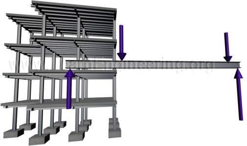 |
| Fig.1 In beam transverse load is acted, and it is an integral part of building structure |
For analysis purpose, a beam can be considered as a part of the beam column system. This way we can determine external load acting on individual beams. After determining load acting on individual beam, beam can be separated out from beam column system for further analysis.
 |
| Fig.2 Building structure consists of many beam-column systems, beam is a part of beam-column system |
Length of the beam is much higher than its lateral dimensions. So axial strain developed in a beam will be very small compared to shear strain, or strain induced due to bending.This is shown in figure below.
 |
| Fig.3 Axial strain in beam is negligible compared to shear strain |
So for design purpose of beams, analysis of shear force and bending moment induced are of the at most importance. The interesting thing is that you can draw shear force and bending moment distribution along any beam, by understanding what exactly is shear force and bending moment.
Both shear force and bending moment are induced in beam in order to balance external load acting on it. We will go through details of it separately.
Shear Force
Shear force is the internal resistance created in beam cross sections, in order to balance transverse external load acting on beam. Consider following beam, it does not matter from where you take a section, when you add forces acting on it, it should be in equilibrium. Shear force is induced exactly for this purpose, to bring the section to equilibrium in vertical direction. It acts parallel to cross section.
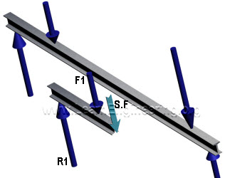 |
| Fig.4 Shear force is induced in a section to balance the external load |
So just by applying force balance in vertical direction on the free body diagram, we can determine value of shear force at a particular cross section. Usual sign convention of the shear force is as follows.
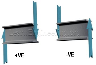 |
| Fig.5 Usual sign convention of shear force |
Now we can apply same concept in different cross section and find out how shear force varies along the length of the beam.
Bending Moment
But balance of transverse forces alone does not guarantee equilibrium of a section. There is another possibility of beam rotation, if moment acting on it is not balanced. If this is the case a bending moment will be induced in cross section of beam, to arrest this rotation. It will be induced as normal forces acting on fiber cross section as shown.
 |
| Fig.6 Bending moment is induced in section to balance external moment, section is zoomed in left figure for better viewing |
Resultant of those forces will be zero, but it will produce a moment, to counter balance the external moment. So we can calculate moment induced at any cross section by balancing the external moment acting on the free body diagram.
Sign convention of bending moment is as follows.
 |
| Fig.7 Sign convention of bending moment for simply supported case |
This sign convention approach is valid for simply supported beam. For cantilever case sign convention is exactly opposite to this.
With these concepts developed, we can easily calculate distribution of shear force and bending moment along the length of the beam. We will see few examples.
Example of Cantilever
Consider this case, a cantilever carrying 3 loads.
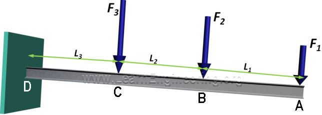 |
| Fig.8 Analysis of cantilever carrying 3 loads |
Here we can start analysis from the free end.
Section A-B
So for between A and B, if you take a section the only external force acting on it is F1. So a shear force should induce in section to balance this force. So value of shear force between A and B is F1. But force balance alone does not guarantee equilibrium of the section. There is an external moment on the section. So a bending moment will be induced in section, in order to balance the external moment. Since value of external moment is F into x, bending moment will vary linearly.
Section B-C
Between B and C effect of force F2 also comes. So shear force becomes, F1 plus F2. And in bending moment effect of F2 also gets added. Similar analysis is done between section C and D also. So SFD and BMD of this problem would look like this.
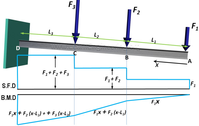 |
| Fig.9 SFD and BMD of cantilever beam |
Simply Supported Case
Now consider this problem. A simply supported beam with uniformly distributed load. First step here would be determination of reaction forces. Since the problem is symmetrical reaction forces will be equal, and will be half of total load acting on beam.
 |
| Fig.10 A simply supported beam with uniformly distributed load in it |
Section A-B
Lets start analysis from point A. If you take section between point A and B, it should be in equilibrium. So shear force will have equal magnitude of Reaction force. Bending moment gives a linear variation.
Section B-C
But after point B, effect of point load and distributed load come. Effect of distributed load is something interesting. Take a section in BC. In this section, along with two point loads there is a distributed load also. This distributed load can be assumed as a point load passing through centroid of distributed load. Value of point load is U( x – L/3). And it is at a distance (x – L/3)/ 2 from section line. So shear force will have one more term, which comes from distributed load. From the equation its clear that shear force varies linearly.
You can easily predict, how bending moment varies along length, from the same force diagrams. Since this equation is quadratic it will have a parabolic shape. Same procedure is repeated in remaining section. Since this problem is symmetrical in nature, S.F.D and B.M.D would also be symmetrical. It is shown in figure below.
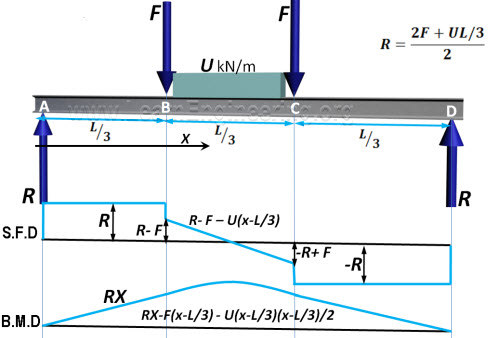 |
| Fig.11 SFD and BMD of simply supported beam |
SOLVED PROBLEMS OF ARCHES
1.A three hinged parabolic arch hinged at the crown and springing has a horizontal span of 12m and a central rise of 2.5m. it carries a udl of 30 kN/m run over the left hand half of the span. Calculate the resultant at the end hinges.

Let us take a section X of an arch. Let ?be the inclination of the tangent at X. if H is the horizontal thrust and V the net vertical shear at X, from theb free body of the RHS of the arch, it is clear that V and H will have normal and radial components given by,
N = H cos ?+ V sin ? R = V cos?–H sin ?
The normal thrust and radial shear in an arch rib.
Parabolic arches are preferable to carry distributed loads. Because, both, the shape of the arch and the shape of the bending moment diagram are parabolic. Hence the intercept between the theoretical arch and actual arch is zero everywhere. Hence, the bending moment at every section of the arch will be zero. The arch will be under pure compression that will be economical.
Difference between the basic action of an arch and a suspension cable
An arch is essentially a compression member, which can also take bending moments and shears. Bending moment and shears will be absent if the arch is parabolic and the loading uniformly distributed.
A cable can take only tension. A suspension bridge will therefore have a cable and a stiffening girder. The girder will take the bending moment and shears in the bridge and the cable, only tension.
Because of the thrust in cables and arches, the bending moments are considerably reduced.
If the load on the girder in uniform. The bridge will have only cable tension and no bending moment on the girder.
Under what conditions will the bending moment in an arch be zero throughout
The bending moment in an arch throughout the span will be zero, if
(i) The arch is parabolic and
(ii) The arch carries udl throughout the span
2.A three-hinged semicircular arch carries a point load of 100 kN at the crown. The radius of the arch is 4m. Find the horizontal reactions at the supports.
VA = VB = 50 kN

Equating the moment about C to Zero, VA * 4 –H*4 = 0
H = VA
Horizontal reaction, H = 50 kN
3.A three-hinged semicircular arch of radius 10m carries a udl of 2 kN/m over the span. Determine the horizontal and vertical reactions at the supports.

Determine H, VA and VB in the semicircular arch shown in fig

Equating moments about A to Zero,
VB * 12 –12 * 9 = 0;
VB = 9 kN and VA = 3 kN
Equating moments to the left of C to zero,
H = VA = 3 kN; H= 3 kN
Distinguish between two hinged and three hinged arches.

Two hinged arches
Statically indeterminate to first degree
Might develop temperature stresses.
Structurally more efficient.
Will develop stresses due to sinking of supports
Three hinged arches
Statically determinate
Increase in temperature causes increases in central rise. No stresses
Easy to analyse. But, in construction, the central hinge may involve additional expenditure.
Since this is determinate, no stresses due to support sinking
Rib –shorting in the case of arches.
In a 2-hinged arch, the normal thrust, which is a compressive force along the axis of the arch, will shorten then rib of the arch. This is turn will release part of the horizontal thrust.
Normally, this effect is not considered in the analysis (in the case of two hinged arches). Depending upon the important of the work we can either take into account or omit the effect of rib shortening. This will be done by considering (or omitting) strain energy due to axial compression along with the strain energy due to bending in evaluating H.
Effect of yielding of support in the case of an arch.
Yielding of supports has no effect in the case of a 3 hinged arch which is determinate. These displacements must be taken into account when we analyse 2 hinged or fixed arches as under

Here U is the strain energy of the arch ?H and ?VA are the displacements due to yielding of supports.
5.A three-hinged parabolic arch has a horizontal span of 36m with a central rise of 6m. A point load of 40 kN moves across the span from the left to the right. What is the absolute maximum positive bending moment that wills occur in the arch

For a single concentrated load moving from one end to the other, Absolute maximum positive bending moment
= 0.096wl = 0.096*40 * 36=138.24 kNm This occurs at 0.211 l = 0.211 * 36 = 7.596 m from the ends.
Absolute maximum positive bending moment = 138.24 kNm at 7.596 m from the ends.
6.A 3 hinged arch of span 40m and rise 8m carries concentrated loads of 200 kN and 150 kN at a distance of 8m and 16m from the left end and an udl of 50 kN/m on the right half of the span. Find the horizontal thrust.

Solution:
(a) Vertical reactions VA and VB :
Taking moments about A,
200(8) + 150(16) + 50 * 20 * (20 + 20/2) –VB (40) = 0
1600 + 2400 + 30000 –40 VB = 0
VB= = 850 kN
VA = Total load –VB = 200 + 150 + 50 * 20 –850 = 500 kN
(b) Horizontal thrust (H)
Taking moments about C,
-H x 8 + VA (20) –200 (20 –8) –150 (20 –16) = 0 -8H + 500 * 20 –200 (12) –150 (4) = 0
H = 875 kN
7.A parabolic 3-hinged arch carries a udl of 30kN/m on the left half of the span. It has a span of 16m and central rise of 3m. Determine the resultant reaction at supports. Find the bending moment, normal thrust and radial shear at xx, and 2m from left support.
Solution:

(1) Reaction at A nd B;
(i) Vertical components of reactions;
Taking moments about A,
-VB (16) + 30 x 82 /2 = 0
– VB (16) + 30 * 32 = 0 VB = 60 kN
VA = Total load –VB = 30 * 8 –60 kN VA = 180 kN
(ii) Horizontal components of reactions at A and

(2) Bending moment at x = 2m from A:
Bending moment = VA (2) –30 * 2 *1 –HA(y) —- (1)

Substitute in (1)y = 1.3125 m at x = 2m fromA’‘.
Bending moment at x = 2m from A = 180 (2) –30 * 2 * 1 –160 * 1.3125
Bending moment at xx = 90 kNm
(3) Radial shear force at x = 2m from A
Shear force, RX = Vx cos ?–H sin ? Where, V = Net vertical shear force at x = 2m from A
= VA – w (2) = 180 –30 * 2 V = 120 kN
H = Horizontal shear force = 160 kN

(4) Normal thrust at x = 2m from A:
Normal thrust PN = Vx sin?+ H cos ?= 120 sin 29º21’+160cos 29º21’ PN = 198.28 kN.
8.A parabolic 3-hinged arch carries loads as shown in fig. Determine the resultant reactions at supports. Find the bending moment, normal thrust and radial shear at D, 5m from A. What is the maximum bending moment

Solution:
(1)Reaction at supports: (RA and RB)
(i) Vertical components of RA and RB : (VA and VB) Taking moments about A,
20 * 3 + 30 (7) + 25 * 10 * (10 +10/2) –VB *(20) = 0 VB = 201 kN
VA = Total load –VB = 20 + 30 + 25 * 10 -201 VA = 99 kN
(ii) Horizontal thrust (H):
Taking moments about the crown point C, considering the right
side of ‘C’,
-VB (20/2) + H (5) + 25 * 10 *5 = 0 -201 * (20/2) + 5 H + 1250 + 0
H = 125 kN (iii) Resultant reactions RA and RB ;

2. Bending moment, normal thrust and radial shear force (at D):

(iii) Normal thrust
P = V sin ?+ H cos ?
V = Net beam shear force = VA –20 V = 99 –20 = 79 kN
Substitute in (iii) P = 79 sin ?+ 152 cos ?= 179.28 kN (iv) Radial shear force
F = V cos ?–H sin ?
F = 79 cos ?–152 sin ?= 2.683 kN
3. Maximum Bending Moment in CB:
Considering a section xx at a distance of ‘x’ fromm B‘’ BMxx = 254KNM
9.A 3-hinged arch is circular, 25 m in span with a central rise of 5m. It is loaded with a concentrated load of 10 kN at 7.5m from the left hand hinge. Find the
(a) Horizontal thrust
(b) Reaction at each end hinge
(c) Bending moment under the load
Solution:

ertical reactions VA and VB:
Taking moments about A, 10(7.5) –VB (25) = 0
VB = 3 kN
VA = Total load –VB = 10 -3 = 7 kN
1.Horizontal thrust (H):
Taking moments about C


10.A three hinged circular arch of span 16m and rise 4m is subjected to two point loads of 100 kN and 80 kN at the left and right quarter span points respectively. Find the reactions at supports. Find also the bending moment, radial shear and normal thrust at 6m from left support.
Solution:

(a) Reaction at A and B:
(i) Vertical components of reactions at A and B:
Taking moment about A,
100 (4) + 80(12) –VB(16) = 0 VB = 85 kN.
VA = Total load – VB = (100+80)-85 VA = 95 kN.
b. Horizontal components of reactions at A and B; Taking moments about the crone points C
VA(8) -H(YC) – 100(4) = 0 95 (8) –H (yC ) –100 (4) = 0
H = 90 kN
(iii)Resultant reactions at A and B:

b) Bending moment at 6m from the left support:

(c) Radial shear force ‘F’ :

R = V cos ?- H sin ?
V = net shear force at x = 6m from A
= VA -100 = 95 –100 = -5 kN H = 90 kN
R = -5 cos (11º32’)–90 sin (11º32’)= – 22.895 R = -22.89 kN

11.A symmetrical three hinged parabolic arch of span 40m and rise 8m carries an udl of 30 kN/m over left of the span. The hinges are provided at these supports and at the center of the arch. Calculate the reactions at the supports. Also calculate the bending moment, radial shear, normal thrust at distance of 10 m from the left support.
Solution:

(1) Reactions at the supports:
(i)Vertical components;
Taking moments about A,

Vertical component of RB, VB = 150 kN
VA = Total load –VB = 30 * 20 –150 = 450 kN
(iii)Horizontal components
Taking moments about the crown, ‘C’,

(22) Bending moment at 10 m from A:

(3)Radial shear force at x = 10m:
R = Radial shear force = V cos ?–H sin ? Where, V = Net vertical shear force at x = 10m from A
H = Horizontal thrust.

Radial shear force, R = V cos ?–H sin ?
R = 150 cos 21º–37548’sin 21º48’
R = 0
(4) Normal thrust at x = 10m from ‘A’:
Normal thrust, N = V sin ?+ H cos ?= 150 sin 21º48’375 cos+ 21?48’ N = 403.89 kN
12.A parabolic 3-hinged arch of span ‘l’issubjected to an u.d.l of w/m run over the entire span. Find the horizontal thrust and bending moment at any section XX.
Solution:

(a) Reactions (Vertical) at the supports:
As the loading is symmetrical, vertical reactions at A and B are equal VA = VB = Total load/2 = wl/2
(b) Horizontal thrust:
Taking moments about the crown point C,

(c) Bending moment at xx;

Tags : Civil – Structural Analysis – Archs
Last 30 days 238 views
Related words :
What is Solved Problems: Archs- Structural Analysis Define Solved Problems: Archs- Structural Analysis Definition of Solved Problems: Archs- Structural Analysis where how meaning of Solved Problems: Archs- Structural Analysis lecturing notes for Solved Problems: Archs- Structural Analysis lecture notes question and answer for Solved Problems: Archs- Structural Analysis answer Solved Problems: Archs- Structural Analysis study material Solved Problems: Archs- Structural Analysis assignment Solved Problems: Archs- Structural Analysis reference description of Solved Problems: Archs- Structural Analysis explanation of Solved Problems: Archs- Structural Analysis brief detail of Solved Problems: Archs- Structural Analysis easy explanation solution Solved Problems: Archs- Structural Analysis wiki Solved Problems: Archs- Structural Analysis wikipedia how why is who were when is when did where did Solved Problems: Archs- Structural Analysis list of Solved Problems: Archs- Structural Analysis school assignment college assignment Solved Problems: Archs- Structural Analysis college notes school notes kids with diagram or figure or image difference between Solved Problems: Archs- Structural Analysis http://www.readorrefer.in – Read Or Refer
|
|
TOP MENU
TECHNOLOGYESSAYSTORYPOEMPROJECTEXPERIMENTENGINEERINGSCIENCEGUIDEHEALTH
OTHER SUGEST TOPIC
![]()
Structural Analysis: Flexibility Method
![]()
Structural Analysis – Moment Distribution Method with Solved Problems
![]()
Solved Problems: Slope Deflection Method- Structural Analysis
![]()
![]()
Solved Problems: Structural Analysis- Influence lines
![]()
Muller Bresalu principle, Begg’s formeterde
![]()
![]()
Deflection Of Determinate Structures
![]()
Important Questions and Answers: Advanced Topics In Bending of Beams
Mechanical Engineering
3th Semester
Strength of Materials – CE6306
Engineering Thermodynamics – ME6301
Fluid Mechanics and Machinery – CE6451
Manufacturing Technology I – ME6302
4th Semester
Manufacturing Technology II – ME6402
5th Semester
Computer Aided Design – ME6501
Heat and Mass Transfer – ME6502
Design of Machine Elements – ME6503
Metrology and Measurements – ME6504
6th Semester
Design of Transmission Systems – ME6601
Automobile Engineering – ME6602
Finite Element Analysis – ME6603
Gas Dynamics and Jet Propulsion – ME6604
7th Semester
Power Plant Engineering – ME6701
8th Semester
Engineering Economics – MG6863
Civil Engineering
3th Semester
4th Semester
Construction Materials – CE6401
Strength of Materials – CE6402
Applied Hydraulic Engineering – CE6403
5th Semester
Structural Analysis I – CE6501
Foundation Engineering – CE6502
Environmental Engineering I – CE6503
Design of Reinforced Concrete Elements – CE6505
Construction Techniques and Equipment and Practice – CE6506
6th Semester
Design of Reinforced Concrete and Brick Masonry Structures – CE6601
Structural Analysis II – CE6602
Design of Steel Structures – CE6603
Railways and Airports and Harbour Engineering – CE6604
Environmental Engineering II – CE6605
Remote Sensing Techniques and GIS – CE6003
Construction Planning and Scheduling – CE6005
7th Semester
Structural Dynamics and Earthquake Engineering – CE6701
Prestressed Concrete Structures – CE6702
Water Resources and Irrigation Engineering – CE6703
Housing Planning and Management – CE6007
Municipal Solid Waste Management – EN6501
Air Pollution Management – CE6011
8th Semester
Prefabricated Structures – CE6016
Repair and Rehabilitation of Structures – CE6021
Higher Secondary School
11th Standard
12th Standard
Tutorial
Science
Recent New Topics :
